Overlapping level heights
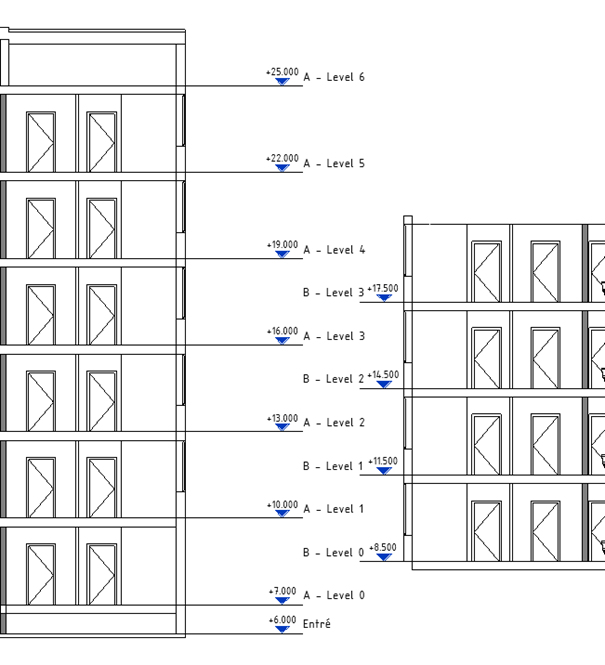
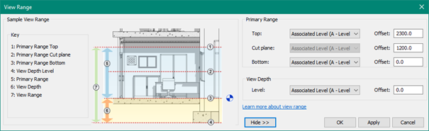
Because what is seen in the view are controlled not only by visibility/graphic override, but as well from View range.
So, in many cases the default cut height of 1200mm is too low or too high.

It is important that everything which should be connected to each floor, is “drawn” / placed on the right view.
i.e. Spaces, which search for walls with elevation 0mm (default value, Computation Height) above placed level.
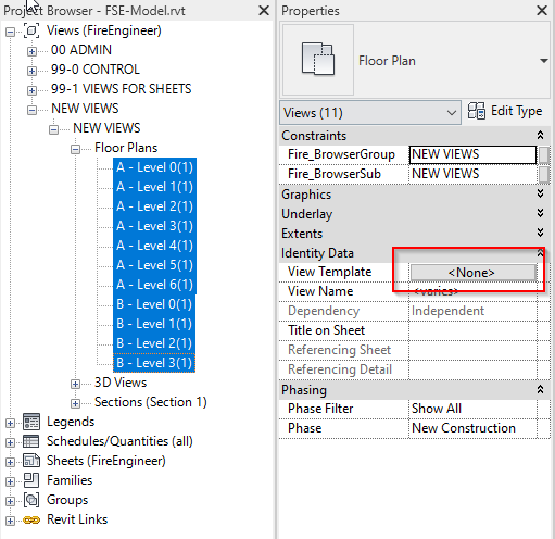
Here it’s important to work with several views, recommended is Work views.
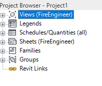
After create original views, create a new set of views and connect them to Fire_WorkViews template.
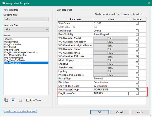
This will move all views in the Project Browser to WORK VIEWS – INITIALS.
Open the view template settings and exclude Fire_BrowserSub.
This will let the user to change the value in Fire_BrowserSub on each individual view.
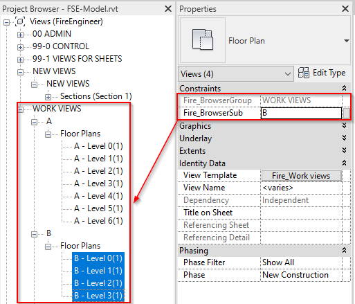
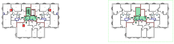
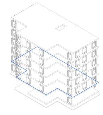
Move all relevant views to new subfolders, in this example A and B, because that is how the Architect defined it in their model.
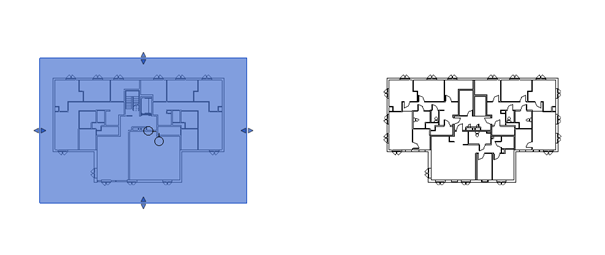
“Hide” all other parts of the building in each view, so only building A are visible in views placed under subfolder A and same with B.
Either use Masking Regions(picture is using this method), Scope boxes or manually update with crop region.
After this, start adding requirements on the different buildings.
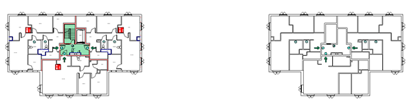
The Views for sheets will probably not look ideal after placing all requirement in the correct building height. There will be a need to do some manual graphical fine tuning on those views.
Note: The right building, no doors are visible and none of the color scheme for evacuation route as well
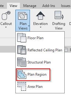
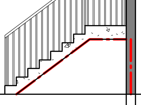
Plan Regions are used to change the view range in certain parts of the floor plan. It can be found under View → Plan Views → Plan Regions
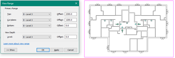
Sketch the area to cover, then change the View range in properties for that area.