Create Evacuation Tag

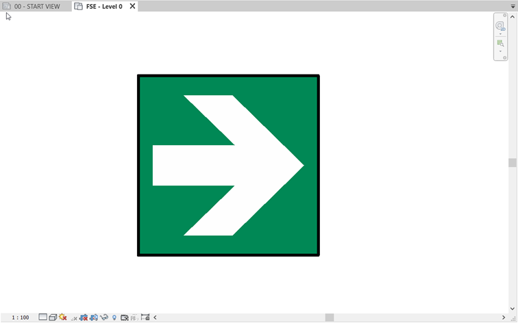
In Revit, place and isolate the component to create a tag from.
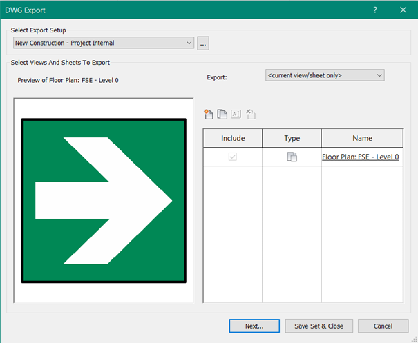
Export the view to DWG.
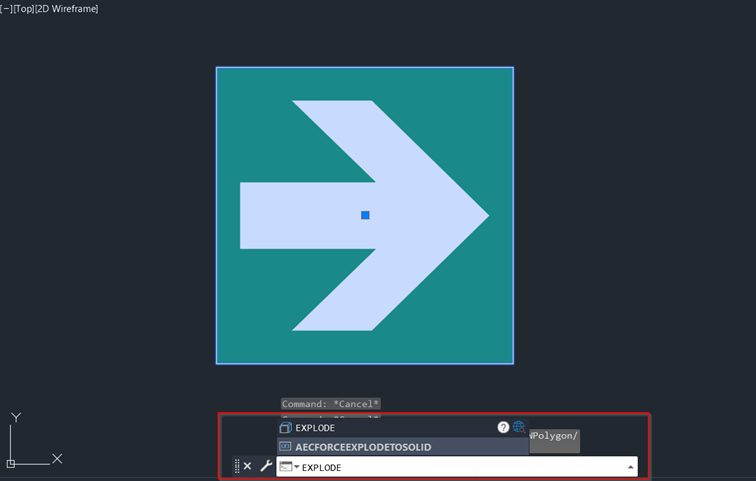
Open the file in AutoCAD. Select the black symbol and explode. Write explode in command.
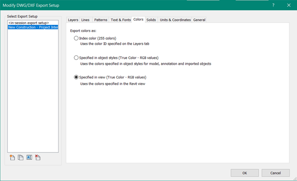
Note: If the colours are not the same in AutoCAD as in Revit, check export settings that colours are set to: Specified in view.
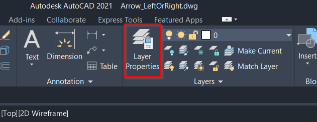
In AutoCAD, go to Layer Properties
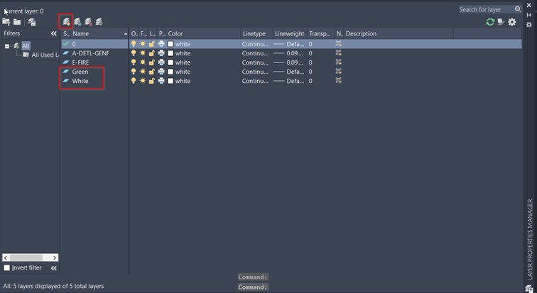
Create new layers for each colour. Name them after the colours, in the BFT template there already exist a few i.e. Red, Green, Blue, Black, White, Black …
These are used to control the colours.
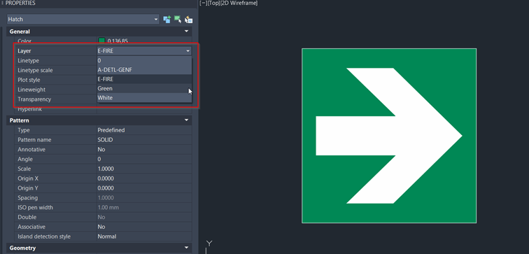
Select corresponding hatches and move them to the new layers.
Note: Change the colour to as layer.
Save the DWG.
Create a new tag, either from new family template, or just use an existing family. In this example an existing family will be modified.
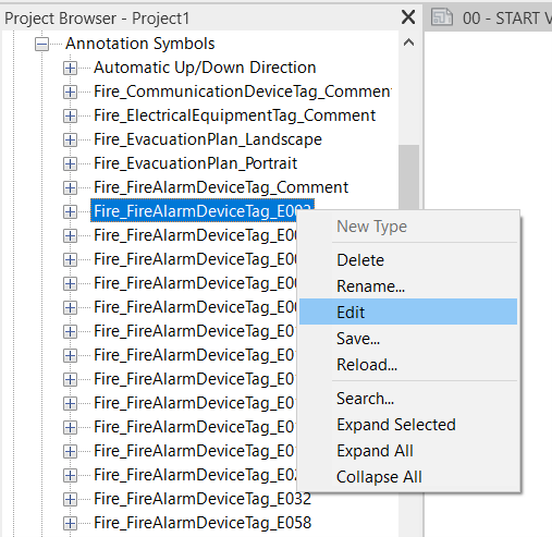
In the project browser, right click on a tag and edit.
Note: the tag must be same category as the symbol in the first step. In this case it will be a Fire Alarm Device
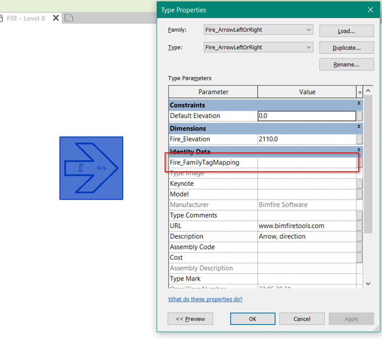
In type properties, change the value in Fire_FamilyTagMapping
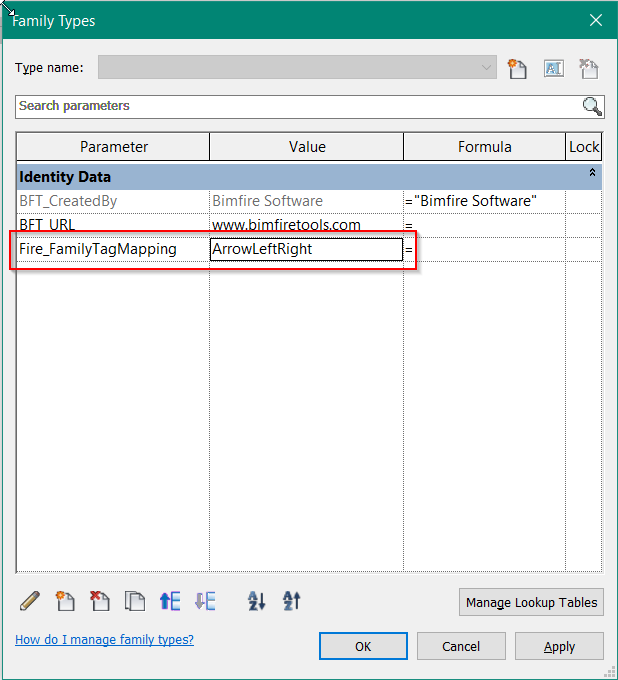
In this example, ArrowLeftRight will be the QUID for this tag.
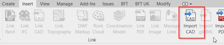
Import the DWG that was created in the beginning and that has been modified.
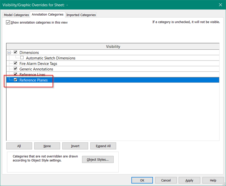
If necessary, turn on Reference Planes in the view via visibility/graphic override.

Scale down the symbol so it’s the right size. All symbol tags included in the BFT template are 6mm tall.
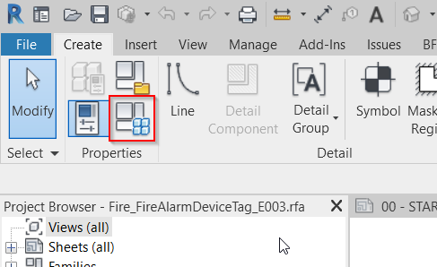
Use the rescale tool found under Modify tab.
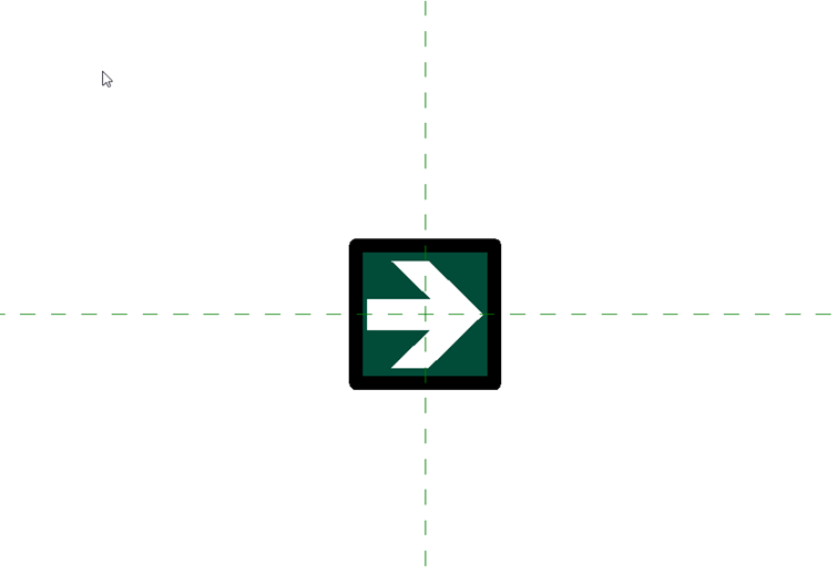
After rescaling, remove the old symbol and place the new ArrowLeftRight in origin (the intersektion of the reference planes)
Save the file and load into the project.